Hope this helps. Let me know if ya need any diagrams?
TIMING BELT
Removal
Disconnect negative battery cable. Raise and support vehicle. Remove right front wheel. Remove engine undercover, if equipped. Remove engine splash shield from right wheelwell.
Loosen, but do not remove, water pump pulley bolts. If accessory drive belt is to be reused, mark belt with arrow to indicate direction of rotation. Turn accessory drive belt tensioner clockwise, and remove accessory drive belt. See Fig. 1.
Remove water pump pulley. Remove serpentine belt idler pulley. Using access hole in bottom of transaxle case to stop rotation of engine, remove crankshaft pulley/vibration damper.
CAUTION:Removal of lower timing belt cover is necessary to avoid damage to timing belt.
Remove lower timing belt cover. See Fig. 2. Working from under vehicle, loosen center bolt of left-hand and right-hand engine support insulators 2 turns. DO NOT remove center bolts.
Lower vehicle. Remove coolant reservoir tank with hoses attached, and set aside. Disconnect cruise control cable (if equipped) from coolant reservoir.
CAUTION:Use a block of wood between oil pan and floor jack, or oil pan may be damaged.
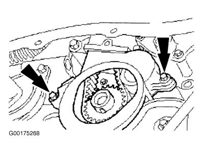
Position floor jack under engine. Raise engine slightly to release pressure from mounting insulator on front of engine. Marking installed position for installation reference, remove engine front support insulator from timing belt end of engine. See Fig. 3.
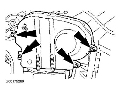
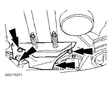
Remove power steering pressure hose bracket from engine lifting eye, and position aside. Remove the timing belt upper cover bolts, but leave the timing belt cover in its installed position. See Fig. 4. Remove the timing belt center cover/front engine mounting bracket. See Fig. 5. Remove the timing belt upper and center covers.
CAUTION:DO NOT pull the spark plug cable when removing the spark plug connectors. If necessary, remove the ignition cables from the ignition coil to avoid kinking the cables. Turn the spark plug connectors slightly before removing to loosen the seal.
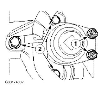
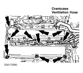
Disconnect throttle cable and cruise control cable from engine appearance cover. Disconnect solenoid valve electrical connector (1), and remove the engine appearance cover (2). See Fig. 6. Pull off the spark plug connectors in line with the spark plugs. Remove the PCV hose. Loosen 10 valve cover bolts from the outside to the inside, working diagonally. See Fig. 7. Remove the valve cover.
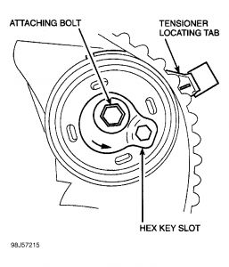
Remove the spark plugs. Turn the engine to TDC on cylinder No. 1. To remove the tension on timing belt, unscrew the timing belt tensioner bolt (1) 4 turns. See Fig. 8. Position the tensioner so the locating tab (2) is at approximately the 4 o'clock position. Line up the hex key slot (3) in the tensioner adjusting washer with the pointer that is located behind the pulley.
CAUTION:To achieve proper tension when installing timing belt, camshaft sprocket bolts must be loose enough to allow sprockets to turn freely on the camshafts.
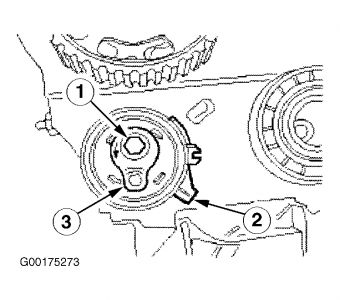
Remove blanking plug (1) from center of exhaust camshaft pulley. See Fig. 9. Loosen, but do not remove, exhaust camshaft sprocket bolt (2). Loosen, but do not remove, intake camshaft sprocket bolt (3). Remove timing belt.
Fig. 1: Removing & Installing Accessory Drive Belt
Courtesy of FORD MOTOR CO.
Fig. 2: Identifying Lower Front Timing Cover Bolts
Courtesy of FORD MOTOR CO.
Fig. 3: Removing & Installing Front Support Insulator
Courtesy of FORD MOTOR CO.
Fig. 4: Locating Upper Front Timing Cover Bolts
Courtesy of FORD MOTOR CO.
Fig. 5: Locating Center Timing Cover Bolts
Courtesy of FORD MOTOR CO.
Fig. 6: Removing & Installing Appearance Cover
Courtesy of FORD MOTOR CO.
Fig. 7: Locating Crankcase Ventilation Hose & Valve Cover Bolts
Courtesy of FORD MOTOR CO.
Fig. 8: Removing Tension From Timing Belt
Courtesy of FORD MOTOR CO.
Fig. 9: Identifying Camshaft Sprocket Holding/Removing Tool
Courtesy of FORD MOTOR CO.
Installation
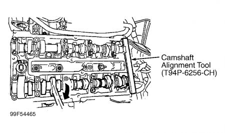
NOTE:To achieve proper timing belt tension, camshaft sprocket bolts must be loosened enough to permit sprockets to turn freely on camshafts. With cam sprocket bolts loose and cylinder No. 1 at TDC, crankshaft must be rotated to TDC in clockwise direction (install camshaft alignment tool in cam slots). Cylinders No. 1 and 4 are at TDC when Woodruff key points straight up.
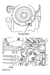
Rotate the crankshaft clockwise to TDC cylinder No. 1. Remove the blanking plug, completely screw in the Crankshaft TDC Timing Peg (303-574, T97-P6000-A), and auto-align the crankshaft to TDC. See Fig. 10.
Hold camshafts with open end wrench. Turn the camshafts to ignition position on cylinder No. 4 and insert the Camshaft Alignment Plate (303-465, T94P-6256-CH) onto the ends of both camshafts. See Fig. 11.
NOTE:DO NOT kink or bend the timing belt less than a diameter of 1.38" (35 mm). DO NOT rotate the crankshaft, and check that it is still resting against the timing pin. The lug of the belt tensioner must not be hooked into the sheet metal cover during timing belt installation.
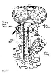
Starting from the crankshaft timing belt pulley and working counterclockwise, position a NEW timing belt in place while keeping it under tension. See Fig. 12.
Apply tension to the timing belt. Incorrect timing belt tension will cause incorrect valve timing. Rotate the tensioner locating tab counterclockwise and insert the locating tab into the slot in the rear timing cover. See Fig. 13.
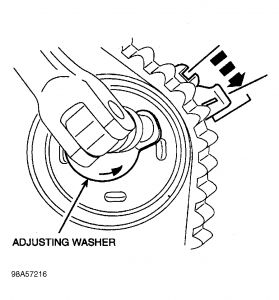
Position the hex key slot in the tensioner adjusting washer to the 4 o'clock position. Tighten the attaching bolt (3) enough to seat the tensioner firmly against the rear timing cover, but still allow the tensioner adjusting washer to be rotated using a 0.24" (6 mm) hex key.
Tension the timing belt, working counterclockwise. Using the hex key, rotate the adjusting washer counterclockwise until the notch in the pointer is centered over the index line on the locating tab (the pointer will move clockwise during adjustment). See Fig. 14.
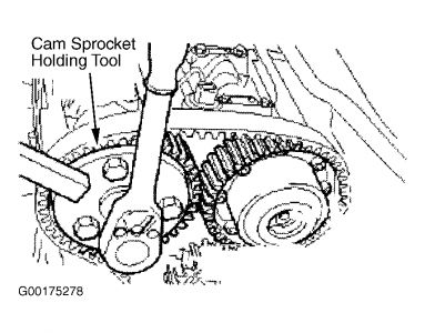
While holding the adjusting washer in position, tighten the bolt to specification. See TORQUE SPECIFICATIONS. DO NOT tighten the camshaft timing pulley bolts against the camshaft alignment plate. Use the camshaft sprocket holding tool to prevent movement. See Fig. 9. The crankshaft must remain at TDC on cylinder No. 1. Tighten the bolts of the intake camshaft timing pulley to specification. Hold the exhaust camshaft by the hexagon with an open end wrench to stop it from turning. Tighten the exhaust camshaft timing belt pulley bolt.
Unscrew and remove crankshaft timing peg. Remove camshaft alignment plate from the camshafts. Turn the crankshaft 2 revolutions in the normal direction of rotation. Check the valve timing by inserting the crankshaft timing peg. Correct it if necessary.
Screw in crankshaft timing peg and make sure that the crankshaft is touching it. Insert camshaft alignment plate into the camshafts. If necessary, loosen the timing pulleys and correct the camshaft alignment. Remove the crankshaft timing peg and camshaft alignment plate. Screw in and tighten the blanking plug on the exhaust camshaft pulley.
NOTE:Coat the inside of the spark plug connectors with silicone grease to a depth of 0.20-0.39" (5-10 mm). Use a blunt object (such as a plastic cable tie) to apply the silicone grease, to avoid damaging the spark plug connectors.
Attach the PCV hose. Coat the spark plug thread with Never Seize, and screw in the spark plugs. Tighten spark plugs to specification. See TORQUE SPECIFICATIONS. Push in the spark plug connector until it engages. Install appearance cover, and tighten bolts to specification. Connect solenoid valve electrical connector and press in rubber seal. Connect throttle and cruise control cables to appearance cover. Put the upper timing belt cover together with the center timing belt cover in place.
Attach the timing belt center cover/front engine mounting bracket. See Fig. 5. Install the valve cover. See Fig. 7. Tighten the valve cover bolts in 2 stages:
Step 1: 18 INCH lbs. (2 N.M).
Step 2: 62 INCH lbs. (7 N.M).
NOTE:Check the seating of the timing belt upper cover gasket and correct it if necessary.
Install the timing belt upper cover. See Fig. 4. Install the front engine mount. Connect the Power Assisted Steering (PAS) reservoir. Install the coolant expansion tank.
Install the power steering pipe bracket to the engine lift eye. Install the front support insulator. See Fig. 3. Remove the floor jack.
Install the coolant expansion tank. Attach the cruise control cable (if equipped) to the coolant expansion tank. Raise and support the vehicle.
NOTE:Verify that the center bolt is centered in the support insulator.
Tighten the center bolt of the right engine support insulator. Tighten the center bolt of the left engine support insulator. Install the lower part of the engine front cover. See Fig. 2. Tighten front cover bolts to specification. See TORQUE SPECIFICATIONS.
NOTE:Use the access hole in the bottom of transaxle case to stop engine rotating.
Install the crankshaft pulley/vibration damper and tighten to specification. See TORQUE SPECIFICATIONS. Install the accessory drive belt. See Fig. 1. Note the accessory drive belt direction mark if belt is being reused. Install the belt idler pulley. Install the water pump pulley.
Tension the belt tensioner clockwise, and position the accessory drive belt in place. Tighten the water pump pulley bolts to specification. See TORQUE SPECIFICATIONS.
Install the right front lower splash shield. Install the engine splash shield (if equipped). Lower the vehicle. Install the right front wheel, and tighten nuts to specification. See TORQUE SPECIFICATIONS.
Connect the negative battery cable. Check the fluid levels and correct as necessary. Check the routing of the vacuum hoses and wiring and secure them with cable ties.
When battery is disconnected, some abnormal driveability symptoms may occur until the PCM relearns its adaptive strategy. The vehicle may need to be driven 10 miles or more to complete a relearn cycle.
SPONSORED LINKS
Monday, November 17th, 2008 AT 9:51 AM